One key change I've made for now is to use the Raspberry Pi model B instead of the model A. This is to avoid problems of attaching the ArduIMU directly to the GPIO pins. The ArduIMU is runs on 5v and the RPI GPIO pins output 3.3v so I would have to get a logic leveler or something to fix this problem. Since I already have a RPI model B (rev 1 though, so it only has 256mb RAM), I decided to take advantage of its extra USB port and not worry about connecting the ArduIMU to the GPIO pins for now. I am also planning on only mounting the ArduIMU on the tube of the telescope so the long FDTI USB cable should work nicely to connect to the RPI anyway.
Wednesday, May 15, 2013
Component Drawing, a few changes
I have created a drawing of the different components of this project. I used a handy tool at https://www.circuitlab.com/. This is only a rough drawing and the placement of the inputs/outputs on the different components is not accurate. It's just to see how everything will connect together.
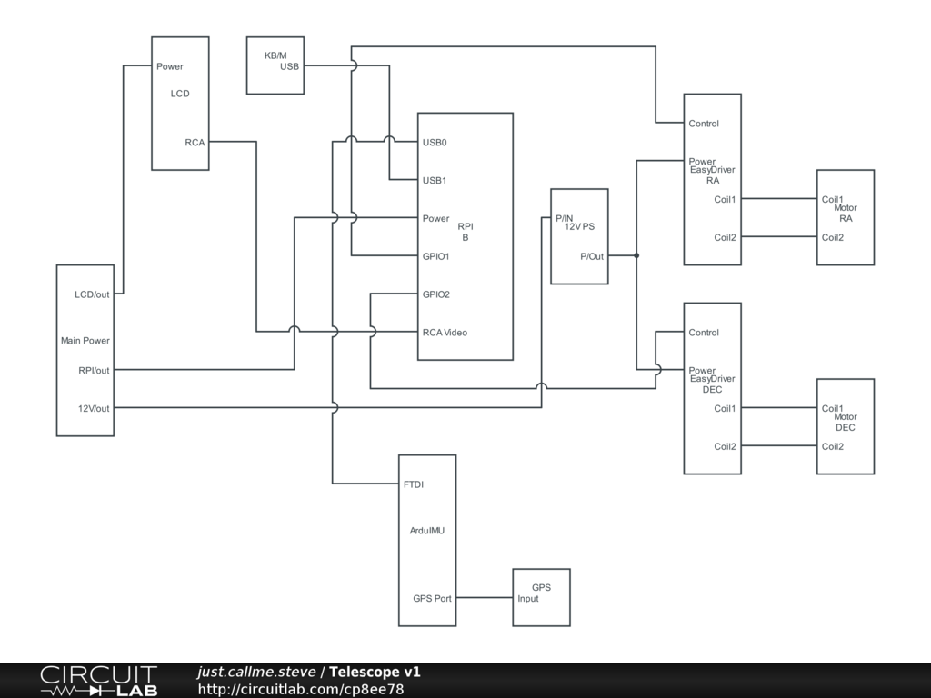
One key change I've made for now is to use the Raspberry Pi model B instead of the model A. This is to avoid problems of attaching the ArduIMU directly to the GPIO pins. The ArduIMU is runs on 5v and the RPI GPIO pins output 3.3v so I would have to get a logic leveler or something to fix this problem. Since I already have a RPI model B (rev 1 though, so it only has 256mb RAM), I decided to take advantage of its extra USB port and not worry about connecting the ArduIMU to the GPIO pins for now. I am also planning on only mounting the ArduIMU on the tube of the telescope so the long FDTI USB cable should work nicely to connect to the RPI anyway.
One key change I've made for now is to use the Raspberry Pi model B instead of the model A. This is to avoid problems of attaching the ArduIMU directly to the GPIO pins. The ArduIMU is runs on 5v and the RPI GPIO pins output 3.3v so I would have to get a logic leveler or something to fix this problem. Since I already have a RPI model B (rev 1 though, so it only has 256mb RAM), I decided to take advantage of its extra USB port and not worry about connecting the ArduIMU to the GPIO pins for now. I am also planning on only mounting the ArduIMU on the tube of the telescope so the long FDTI USB cable should work nicely to connect to the RPI anyway.
Subscribe to:
Post Comments (Atom)
No comments:
Post a Comment